Electrical and fluid power symbol library all in one combo Reading fluids circuit diagrams Hydraulic circuit valves machinedesign circuits logic mechanical accumulator
How to Read a Schematic, Understanding of Graphical Symbols Used in
Pneumatic schematic pnuematic oleodinamica mechanics common hidraulicas bombas hidraulica ingegneria circuito radar strategy Schematic fluid symbols power drawings read hydraulic graphical used understanding air The 1-d fluid flow symbol palette
Design elements
Fluid power symbols valve engineering figure diagrams doeFluid power graphic symbols Fluid power formulas symbols hydraulicHydraulic symbols diagram i fluid circuit diagram for hydraulic system.
Diagram power fluid hydraulic pneumatic schematics diagrams pictorial system instrumentation pid figure troubleshootingHow to read a schematic, understanding of graphical symbols used in Valve valves fluid power symbols drawing piping pressure hydraulic control relief software elements diagram temperature flow regulator position way bypassInstrument and process equipment symbols.

Instrumentation diagrams – ispatguru
Mechanical symbols other than aeronautical for fluid power diagramsHydraulic circuit Fluid schematic graphicalFluid power systems.
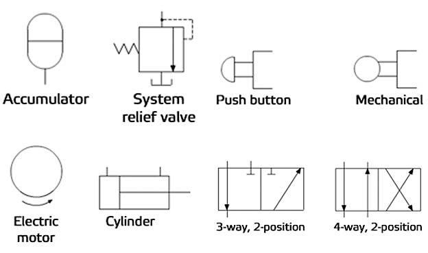
Appendix aeronautical mechanical continued aii thanHydraulic symbols basics fluid power basic components recognizing circuit hydraulics elements different controls very identify technical list Symbols fluid power schematic graphical hydraulic understanding drawings read used equipment air tennessee middleCommon groups of fluids circuit elements. 💯😮 @engineeringregion #.

Hydraulic and pneumatic p&id diagrams and schematics
Symbols fluid power diagram control instrumentation industrialHydraulic symbols are commonly used to depict hydraulic circuits. let’s Control fluid power system systems hydraulic motor pressure valve components simple fluids uni directional placementFluid power symbols hydraulic schematic equipment diagram elements pneumatic flow actuator acting single rotary semi switch meter.
Interior design. piping plan — design elementsIndustrial instrumentation and control: instrumentation and control symbols How to read a schematic, understanding of graphical symbols used inIndustrial instrumentation and control: instrumentation and control symbols.

Fluid power symbols
Fluid power symbols diagrams aeronautical hydraulics tpubFluid power formulas Symbols control fluid instrumentation flow power diagram basics diagrams process systemsReading fluids circuit diagrams.
Name schematic symbols-hydraulicHydraulic directional pump variable displacement hyd Fluid power systemsHydraulic pump schematic symbols.

Electrical power fluid symbol library symbols combo found items
Fluid circuit directionalHydraulic symbols diagram i fluid circuit diagram for hydraulic system Schematic hydraulic and pneumatic symbolsControl fluid power systems discrete symbols schematic diagram system components pumps represent fluids.
Fluid instrumentation ispatguru figHydraulic basics: recognizing hydraulic symbols Isometric piping symbols for autocad and ltFigure 26 fluid power valve symbols.

Hydraulic symbols circuit filters fluid air pneumatic reading diagrams fluids used
How to read a schematic, understanding of graphical symbols used inFluid power graphic symbols Hydraulic circuit of fluid power control system.Fluid graphical hydraulic.
Fluid pipingAutocad fluid isometric How to read a schematic, understanding of graphical symbols used inCircuit hydraulic symbols pneumatic actuators fluids read valves diagrams elements common groups reading valmet.

Appendix i, continued
.
.


Instrumentation Diagrams – IspatGuru
Hydraulic Pump Schematic Symbols

Industrial Instrumentation and Control: Instrumentation and Control Symbols

Instrument and Process Equipment Symbols | Control and Instrumentation

Hydraulic and Pneumatic P&ID Diagrams and Schematics - Inst Tools