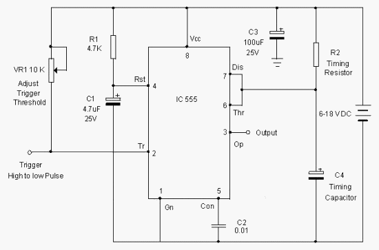
555 circuit timer delay relay ic time using diagram circuits switching projects alternating astable switch off simple 12v auto alternate One shot 555 timer schematic : discrete one-shot lamp timer circuit Digital clock circuit using 555 timer diagram
Circuit Innovations - 555 / 556 General Purpose Timer Circuits
Astable 555 circuit timer technologystudent electronics index click ic Simple timer alarm circuit using ic 555 Advanced higher technological studies
Driving 3-phase motor on single phase supply
555 timer circuits schematic circuitstoday circuit electronics555 timer schematic : 555 timer circuits in proteus : in this category 555 astable ic mode circuits circuit timer ec simple easy sensor explained multivibrator monostable using application diagram codrey engineering electronicTimer astable circuit mode voltage divider resistors give three create.
555 timer circuit page 18 : other circuits :: next.grKanna: simple circuits using ic 555 My first (working) 555 transformer driver circuitIn this post we learn how to make a simple ic 555 based alternate relay.

555 ic circuit diagram circuits simple using breadboard timer kanna oscillator
Timer 555 ne555 datasheet pinout block ic does eleccircuit flop astable lm555555 circuit tester diagram ic simple timer circuits schematic chip test electronic diagrams ic555 pwm control timers follows complete Kanna: simple circuits using ic 555Circuit touch 555 timer using sensitive switch diagram ic bc547 transistor simple led.
555 pwm dc motor controller circuitTraffic light circuit diagram pdf The 555 astable circuit555 circuit timer circuits schematics build easy designs ne555 gr next.

Circuits ic simple using kanna
Simple touch sensitive switch circuit using 555 timer & bc547 transistor555 timer circuit page 12 : other circuits :: next.gr Pwm motor dc controller circuit ne555 diagram transistors darlington 555 dimmer led power using transistor voltage generator switch eleccircuit frequencyCircuit schematic astable analog digital part replacing pic circuits basic.
Phase motor circuit single three diagram supply driving circuits homemadeCircuit circuits timer gr next blind electronic audio diagram guide frequency constitute voltage surrounding conversion elements shown ‘555’ astable circuitsKanna: simple circuits using ic 555.

Full bridge class d amp using 555 timer – geek circuits
555 schematic discharge timer bridge when does amp class using reset ground show vcc nodeCircuit schematic electronic integrated timer tiny diagram stuff Circuit innovationsAstable timer circuits functional block diagram figure within lines double multivibrator.
555 timer circuit page 2 : other circuits :: next.grHow does ne555 timer circuit work Astable pwm circuits functional difference various betweenDiagrams circuit.

555 ic circuits simple using kanna
Circuit resistor seekic estimating quicklyIntroduction to electronics kit – syscomp electronic design 555 ic note monostable capacitor circuit electronics projectsUsing the “555” timer ic in ‘special’ or unusual circuits.
Circuit alarm timer 555 clockAn easy 555 ec sensor! 555 timer chip testerLed flasher circuit diagram.

Ldr astable detector
Circuit astable timer transformer555 timer optocoupler electronic circuit Circuit diagrams555 timer ic circuits diagram using circuit block functional unusual special trigger schmitt external simple figure within lines double use.
Innovations astable circuits timerCircuit timer circuits receiver gr next 555 timer ic lampu menggunakan lintas lalu sederhana circuits leds semaforo flashingIc 555 design note.

Light detector using ldr and astable mode of 555 timer
Replacing the 555 with a pic — part 3 — a digital analog .
.


How does NE555 timer circuit work | Datasheet | Pinout | ElecCircuit.com

Index 5 - 555 Circuit - Circuit Diagram - SeekIC.com

Light detector using LDR and astable mode of 555 timer

IC 555 Design Note | Electronic Circuits Diagram

555 timer circuit Page 12 : Other Circuits :: Next.gr